I actually got the number off the title app not the motor itself. The weatehr is supose to be better so I'll get it off the engine itself and take some pictures with the cover off. The engine was rebuilt in 1991 so I wonder if it was converted or something at that time.
TinBoats.net
The original aluminum boat site!
You are using an out of date browser. It may not display this or other websites correctly.
You should upgrade or use an alternative browser.
You should upgrade or use an alternative browser.
Can't kill engine
- Thread starter user 7806
- Start date


Help Support TinBoats.net:
This site may earn a commission from merchant affiliate
links, including eBay, Amazon, and others.
benjineer
Well-known member
I'm pretty sure grounding that Salmon wire should kill the engine. That's the way kill circuits usually work. Do it with the cover off with a jumper wire. From a terminal connection under the cover. If that works, check continuity of the salmon wire from the point you touched the jumper wire to the back of the ignition switch. If that checks good, I'd say your ignition switch is bad or the ignition switch ground (black wire) is disconnected/broke, etc. You can check the switch. You should have continuity between the black and salmon wires on the back of the switch when the switch is off. You could also check continuity of that black wire on the back of the ignition switch to the ground terminal of the battery. Bad grounds can make all kinds of weird things happen that make you scratch your head - gauges going haywire when you turn the key, etc.
You could connect the salmon wire back to the kill button and if the button works, kill it that way. I'm not sure I understand the reasoning behind cutting the wire and disabling the old kill button (instructions on diagram). They could've just run a second wire and allowed you to kill it with the switch or the button. Of course that may lead to accidentally leaving the switch in the "on" position if you killed it with the button. That's probably why they cut the wire.
You could connect the salmon wire back to the kill button and if the button works, kill it that way. I'm not sure I understand the reasoning behind cutting the wire and disabling the old kill button (instructions on diagram). They could've just run a second wire and allowed you to kill it with the switch or the button. Of course that may lead to accidentally leaving the switch in the "on" position if you killed it with the button. That's probably why they cut the wire.
JMichael
Well-known member
That's pretty much what they did on the 75 model's wiring so it could be killed with either method.benjineer said:I'm pretty sure grounding that Salmon wire should kill the engine. That's the way kill circuits usually work. Do it with the cover off with a jumper wire. From a terminal connection under the cover. If that works, check continuity of the salmon wire from the point you touched the jumper wire to the back of the ignition switch. If that checks good, I'd say your ignition switch is bad or the ignition switch ground (black wire) is disconnected/broke, etc. You can check the switch. You should have continuity between the black and salmon wires on the back of the switch when the switch is off. You could also check continuity of that black wire on the back of the ignition switch to the ground terminal of the battery. Bad grounds can make all kinds of weird things happen that make you scratch your head - gauges going haywire when you turn the key, etc.
You could connect the salmon wire back to the kill button and if the button works, kill it that way. I'm not sure I understand the reasoning behind cutting the wire and disabling the old kill button (instructions on diagram). They could've just run a second wire and allowed you to kill it with the switch or the button. Of course that may lead to accidentally leaving the switch in the "on" position if you killed it with the button. That's probably why they cut the wire.
I hooked up a wire from the button to the Salmon wire on the junction block. For the most part when you press the button it kill the motor. I think I need to take it apart and clean the contacts for it to me reliable.
The ground on the boat is strange for sure. The previoius owner in places was using the boat itself as a ground and my understanding is that this is wrong and it will cause corrosion. I'm ordering a Blue Sea fuse box with a ground bar so I will be rewiring the boat or at aleast a lot of it.
Thanks for the info on the key switch I will trace those wires down and see it I can locate the problem.
Here some pictures of the motor, I checked the serial # on the plate and it's the same as above.
The black spiral tubing is only temporary, I didn't have enough wire of enough different colors so I ordered enough wire to rewire the motor. At West Marine you can buy the marine wire by the foot.
Attachments


JMichael
Well-known member
Well I don't see an ignition module on it so I suspect the front cover is off of a later model motor that had thunderbolt ignition. Is your motor a tiller control with a remote ignition switch mounted somewhere?
JMichael said:Well I don't see an ignition module on it so I suspect the front cover is off of a later model motor that had thunderbolt ignition. Is your motor a tiller control with a remote ignition switch mounted somewhere?
Yes it's a tiller, the ignition switch is on a panel with the electric choke button are mounted in a panel on the right side behind the rear seat. Can't make up my mind of I like it there or not.
JMichael
Well-known member
Oh ok. I knew you had mentioned the key switch but I didn't see any cables in the pics and I was thinking it was remote controlled because it had a key switch. Since I just converted mine to tiller control, I'm just going to try to install a starter button on the front of the engine. I won't need to wire or use the electric choke since I'll be right there at the engine to use the manual choke. I saw a video on youtube where a guy had done this but can't find it now.
cajuncook1
Well-known member
- Joined
- Mar 24, 2010
- Messages
- 437
- Reaction score
- 1
Gramps50 said:JMichael said:Well I don't see an ignition module on it so I suspect the front cover is off of a later model motor that had thunderbolt ignition. Is your motor a tiller control with a remote ignition switch mounted somewhere?
Yes it's a tiller, the ignition switch is on a panel with the electric choke button are mounted in a panel on the right side behind the rear seat. Can't make up my mind of I like it there or not.
If you post your question at AOMCI (Antique Outboard Motor Club, Inc), you should get your answer. Ask for Dave Benard, Jason Baxtor, or JW in Dixe, those guys really know there Mercury motors. They rebuild them, race them, and give excellent advice. (Motors from 1940's to 1980's)
Here is the link
https://www.aomci.org/cgi-bin/yabb2/YaBB.pl?board=askamember
JMichael said:Oh ok. I knew you had mentioned the key switch but I didn't see any cables in the pics and I was thinking it was remote controlled because it had a key switch. Since I just converted mine to tiller control, I'm just going to try to install a starter button on the front of the engine. I won't need to wire or use the electric choke since I'll be right there at the engine to use the manual choke. I saw a video on youtube where a guy had done this but can't find it now.
I was watching a Youtube video when the key was in the top of the case on the right side are you were facing the motor. Didn't show the installation just him running it and starting with both the key and pull rope. https://www.youtube.com/watch?v=q-7Ad5OcGkg
Thanks cajuncook1 took a peak what an interesting place. Just in a quick browse I found a replcement float for the old metal fule tank.cajuncook1 said:If you post your question at AOMCI (Antique Outboard Motor Club, Inc), you should get your answer. Ask for Dave Benard, Jason Baxtor, or JW in Dixe, those guys really know there Mercury motors. They rebuild them, race them, and give excellent advice. (Motors from 1940's to 1980's)
Here is the link
https://www.aomci.org/cgi-bin/yabb2/YaBB.pl?board=askamember
Look for an quarter size freeze plug on the side of the motor.That should have your motor serial # on it if it hasn't been replaced. [-o<
Merc went through alot of different ignitions in the earlier years.I know 71 & 75 are different.
You have to make sure what ignition you have to get the right wiring diagram to proceed with your trouble shooting.When you convert to remote controls some of the wiring may be changed under the cowl.
Understanding your electrical system will make trouble shooting much easier.With the Mercs stay away from the after maket service manuals,they just seem to group them all together. [-X
If you continue to have problems you can PM me.
Craig
JMichael said:That's pretty much what they did on the 75 model's wiring so it could be killed with either method.benjineer said:I'm pretty sure grounding that Salmon wire should kill the engine. That's the way kill circuits usually work. Do it with the cover off with a jumper wire. From a terminal connection under the cover. If that works, check continuity of the salmon wire from the point you touched the jumper wire to the back of the ignition switch. If that checks good, I'd say your ignition switch is bad or the ignition switch ground (black wire) is disconnected/broke, etc. You can check the switch. You should have continuity between the black and salmon wires on the back of the switch when the switch is off. You could also check continuity of that black wire on the back of the ignition switch to the ground terminal of the battery. Bad grounds can make all kinds of weird things happen that make you scratch your head - gauges going haywire when you turn the key, etc.
You could connect the salmon wire back to the kill button and if the button works, kill it that way. I'm not sure I understand the reasoning behind cutting the wire and disabling the old kill button (instructions on diagram). They could've just run a second wire and allowed you to kill it with the switch or the button. Of course that may lead to accidentally leaving the switch in the "on" position if you killed it with the button. That's probably why they cut the wire.
Been checking wires all afternoon here's what I have come up with so far.
There is conectivity in the Salmon wire from the switch to the junction block on the motor.
There is conectivity in the Black wire from the switch to the motor.
There is conectivity between the salmon & the black no matter where the key is, on/off/start makes no difference
Press the kill switch on the motor and the conectivity between the slamon & black is broken, which kills the engine most of the time.
If I look at the wiring diagram which shows 4 wires on the back of the switch & this looks like mine in the off position it show not conectivity between any wires.
I just took off the wire from the kill button to jusction block that has the slamon wire connections on it. Now the key switch shows no conectivity when the switch is off & when it is on there is conectivity between the black & salmon.
From the previous test I would have to say that turning the switch off should kill the engine. I have sprayed some lock lube in the switch and I haven't been out to test it.
I checked the conectivity between the kill switch, it has connectivity to ground until you press the the button. So now I'm really confused.

I can see I need a barrel so I can run the motor and work on it in the yard.
Found the correct wiring diagram, I think at least it says it for a 70-71 Merc 200

JMichael
Well-known member
Gramps50 said:Been checking wires all afternoon here's what I have come up with so far.
There is conectivity in the Salmon wire from the switch to the junction block on the motor.
There is conectivity in the Black wire from the switch to the motor.
There is conectivity between the salmon & the black no matter where the key is, on/off/start makes no difference
Press the kill switch on the motor and the conectivity between the slamon & black is broken, which kills the engine most of the time.
If I look at the wiring diagram which shows 4 wires on the back of the switch & this looks like mine in the off position it show not conectivity between any wires.
I just took off the wire from the kill button to jusction block that has the slamon wire connections on it. Now the key switch shows no conectivity when the switch is off & when it is on there is conectivity between the black & salmon.
From the previous test I would have to say that turning the switch off should kill the engine. I have sprayed some lock lube in the switch and I haven't been out to test it.
I checked the conectivity between the kill switch, it has connectivity to ground until you press the the button. So now I'm really confused.
I can see I need a barrel so I can run the motor and work on it in the yard.
Found the correct wiring diagram, I think at least it says it for a 71-72 Merc 200
Actually, it says it's for 70-71 not 71-72. :lol:
That schematic is very similar to the one my seloc manual has but there are some differences still. I think the first thing you have to do is make a definite determination of what motor you have since that is going to be critical to figuring out what the wiring should look like.
Every small engine ign system I've ever worked with involved grounding the ign system one way or another to kill the engine. The fact that your ground (based on your test) seems to be connected to the ign system at all times except when the kill switch is pressed, is puzzling to say the least.
Your right I changed it in my orginal post, thanks.
I now have enough wire to rewire the motor and replace all the wire with instalation off. So to the where the wire are on the stator I will have to remove the flywheel so I should then be able to tell if it's points or electronics.
I also need to find the freeze plug wtth the serial # on it and see what it says.
If you look at either of the wiring diagrams it appears when the switch is on M (salmon) & G (black) are connected the same is true on start but not when Off.
I'm like you normally when you want to kill and engine you ground the ignition,
JMichael
Well-known member
Well let me offer these to further add to the confusion. :lol: These are pics of the schematics from my seloc manual. The first one is listed as the electric start 65-71 model motors.
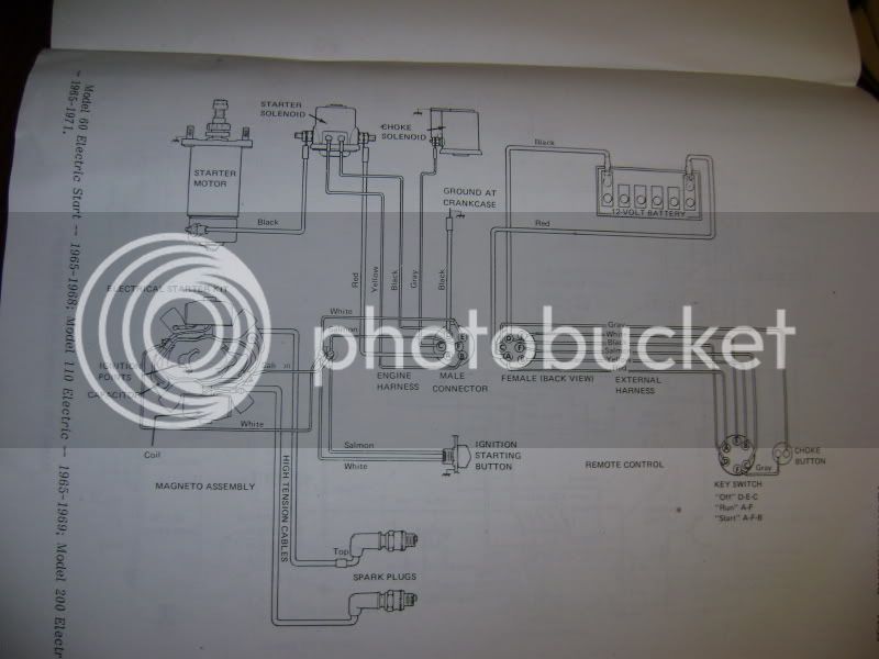
You'll probably notice right away that they listed the kill button as a starter button. I feel pretty safe saying it's supposed to be the kill button since it doesn't even remotely affect the voltage to the starter solenoid or the starter. :mrgreen: In this example, they are preforming the kill function by joining the salmon/white/black wires together. Whether it's done by the kill button or the ign switch being turned to the off position. This system also uses a magneto with internal coils vs a stator.
Next is the 72 stator system with external coils.
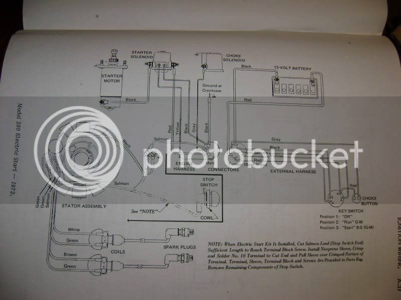
Any ways, I hope these help rather than confuse you, in trying to figure out what's going on with your wiring.
You'll probably notice right away that they listed the kill button as a starter button. I feel pretty safe saying it's supposed to be the kill button since it doesn't even remotely affect the voltage to the starter solenoid or the starter. :mrgreen: In this example, they are preforming the kill function by joining the salmon/white/black wires together. Whether it's done by the kill button or the ign switch being turned to the off position. This system also uses a magneto with internal coils vs a stator.
Next is the 72 stator system with external coils.
Any ways, I hope these help rather than confuse you, in trying to figure out what's going on with your wiring.
I actually have both of the same schematics, I'm going to say the 1st one definitly isn't it as my coils are external as in picture #2. My kill switch button only has one wire going to it and then grounds to the case. Using an ohms meter it is normaly closed.
I was told that the engine was rebuilt in the 90's so maybe something in the ignition was upgraded. Probably next week I'm going to rewire it, so I will get further into it at that point and maybe can clear some of this up.
Thanks to everyone for their help and advice, even though we haven't solved the issue yet I have gained a wealth of knowledge about my motor.
JMichael
Well-known member
Gramps50 said:I actually have both of the same schematics, I'm going to say the 1st one definitly isn't it as my coils are external as in picture #2. My kill switch button only has one wire going to it and then grounds to the case. Using an ohms meter it is normaly closed.
I was told that the engine was rebuilt in the 90's so maybe something in the ignition was upgraded. Probably next week I'm going to rewire it, so I will get further into it at that point and maybe can clear some of this up.
Thanks to everyone for their help and advice, even though we haven't solved the issue yet I have gained a wealth of knowledge about my motor.
That clears things up a little for me then. With the normally closed kill button, that would mean that it removes the ground from the stator in order to kill the engine. That would also explain the reason for removing the kill button from the circuit when adding a key switch. If the kill button was still supplying a ground, then the key switch wouldn't be able to remove the ground and kill the engine. Seems like a strange design compared to what I'm use to seeing but at least it's starting to make sense now.
JMichael said:That clears things up a little for me then. With the normally closed kill button, that would mean that it removes the ground from the stator in order to kill the engine. That would also explain the reason for removing the kill button from the circuit when adding a key switch. If the kill button was still supplying a ground, then the key switch wouldn't be able to remove the ground and kill the engine. Seems like a strange design compared to what I'm use to seeing but at least it's starting to make sense now.
Yea that explained why when I fist hooked up the button it would not kill the engine, I thought the contacts were dirty. Later I was able to use it to kill the motor, guessing that at that point I had the key off, which would then allow the motor to be killed.
Here's my thought now so that either the key switch or the button would kill the engine is take the ground wire for the ignition and run it through the button, then I think if you turned the switch off or pressed the button the motor should die.
JMichael
Well-known member
Gramps50 said:Here's my thought now so that either the key switch or the button would kill the engine is take the ground wire for the ignition and run it through the button, then I think if you turned the switch off or pressed the button the motor should die.
Yea, it would require some extra wiring but it should work both ways then.
JMichael said:[Yea, it would require some extra wiring but it should work both ways then.
If I'm see it right there is a ground wire from the ignition that goes to a screw on the motor head. There is a junction block close that how has the salmon wires on it & a vacant post. So I'm thinking I could use it. Worrth as try as that way it wouldn't require a much to try it. If it works leave it if not put it back the way it was.