Need help understanding this electronic thing

TinBoats.net

Help Support TinBoats.net:

This site may earn a commission from merchant affiliate links, including eBay, Amazon, and others.

ChitownBasser

Well-known member
Joined
Feb 7, 2012
Messages
111
Reaction score
0
Hey fellas. My modifications to my 14' boat is going great thanks to this site. I've read a lot of posts and learned from most of them. I am almost to the point where I have to start thinking about electrical hook ups (lights, fishfinder, etc.).
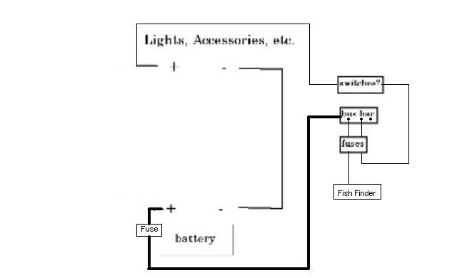
From what I have read in this forum, I know the trolling motor should be hooked straight to the batter with an inline fuse. Right? Hook the fish finder straight to the battery, right? Which brings me to the lights. I want to use switches for the lights. I understand that I need fuses and a bus bar (not sure what it is). I have included a diagram that I need help completing. I am not how to rig it up. I am still going back and reading past posts to get an idea. btw I have a 12v Bass Pro Shops Deep Cycle Battery.

electric.jpg
 
In laymans terms a bus bar is just a junction point. It's a strip/ bar that your battery gets hooked up to and then has multiple points to connect electrical items. You can think of it as a "splitter" for your positive cable. It can also be used for a negative to gather up all your grounds on the way back to the battery. Separate bars that is, not the same one!

;)

Anything hooked up to the battery should be fused as close to the battery as possible. This is because if your wiring shorts, it will be "down stream" of the fuse. The fuse pops and there's no more current, thus no more sparks flying. A 12v battery can create an arc you can weld with. It can blow right through aluminum before you can blink if it shorts. Don't be paranoid about electrocution or something like that. I'd be more worried about a short blowing a hole in the side of the boat while on the water. It's all very unlikely, but a fuse is your protection against a bad day. Make sure your wires are run neat and tidy, don't cross over any sharp edges and you'll be good.

Heres what I used for my lights, bildge, etc:

d572b90a.jpg


Think I paid 25 bucks at the boat shop. All my switches and circuit breakers in one neat package. Lighted switches and all labeled. CB's are better than a fused panel IMO, you're never stuck digging around in the bottom of the boat for your replacement fuses.

Good luck on your build.
 
With All Due Respect...

What you are asking is for someone to submit an electrical schematic for your application and describe in detail how to go about putting it all togeter. I would submit that is far beyond the scope of this forum. There are many of us on here who have done this stuff for quite a while, both as hobbiests and as professionals. There are a lot of knowledgable guys here and all are willing to help, but everyone's time is valuable and inspite of the best of intentions, no one has the time to write an A-Z course on marine wiring. Given your level of electrical ability, I would suggest doing some research and some self education. There is a lot of information in the threads here for the reading, and Google will yield volumes of good information. Then come back with questions on doing a specific task, and I'm sure someone here will be able to help you out, but what you are asking at this ppint is just too much to respond to.
 
Since I'm just sitting here having my coffee, I thought I'd take a stab at trying to get you headed in the right direction. To save time, I've just modified your drawing. Component location is going to be unique to your setup, but this should give you an idea. You'll need to feed the (buss bar/terminal strip) with a wire large enough gauge to handle the draw of all the devices combined. If your fuse box is not next to the battery, I'd suggest a main line fuse/breaker next to the battery, rated for the max draw of all the devices on at once. From the buss bar, you only need a wire gauge suitable for that devices amp draw. This will run to your fuse panel and from there to a device or switch, depending on whether the device is switched or straight wired. As far as your individual fuses, you'll need to figure out what the correct size would be for each device. But sitting down and laying it all out on paper before you actually start would be a good start at doing a neat and safe job with your wiring.

f43e8712.jpg


If I've left out anything or made errors, maybe someone else will offer that info.
 
I ran two circuit breakers in there one to the trolling motor and one to the fuse panel. Depending on where your battery is front or back of the boat. Autozone sells a 6 slot blade type fuse holder thats what I used on my boat then from the fuse holders to the individual switches. I even run my fish finder on a switch so I turn all of the switches off then everything is off just in case I leave the fish finder on. There is going to be more than one wire from the fuses to the switches. The fuse holder that I used has a positive wire coming in and goes to all of the fuses so its a buss bar and fuse holder in one. Everyone wires things different but this is how I would do it. Its really up to you on how you wire it up.

Steve
 

Attachments

  • electric.jpg
    electric.jpg
    24.2 KB · Views: 957
Man I feel your pain. I am at the same point on a elect only lake rig, planning on 6-6v bank for minnie 101tm and a 12v for gadgets and another 12v for the BM. gonna be heavy, but hoping the all alum work will make it all a nice package. I was just sorting out my toys and the fish finder inst book says connect direct, it also says do not connect to bus bar. I am leaning toward a piece of that man made recycled plastic that looks like wood for a back board and mounting everything to it. I picked up a nice wp switch panel with the ato blade type fuses and led switch face,I think I got it from cabelas, you can go crazy and broke going thru this stuff, I also found really cool courtesy lights that are led for less than $5 ec at 1st choice marine, they go in and out of stock, just looked the other day and they were in stock, they come in red and white, the best part is a greenlee punch for elect conduit is an exact match for the needed hole size, I will have a switch for red and one for white spreading them throughout the boat, they only draw .02a, I also found compact 12v disconnect switches at westmarine for about $30, they turned out to be real nice and not as huge as the perkos.
 
Well I just got finished wiring mine up with advice from here and it went pretty easy once you get started.

I am no expert but here is what I did.

First buy a fuse holder with a ground bar attached. Academy 29 bucks.

Attach your hot wire and neg wire where it shows on the diagram. Then start running your accessories.Use the proper fuse for the amps being pulled. The amperge of each accessory can be found on the package.

If you are using low amp lights like I did. .050 amps you can run all your hot linesl together onto one line and Negatives all on another. Then run those line to one fuse on the fuse box.

I ran all my interior lights to one
I ran my depth finder to one
I ran my running lights to one
Then I ran my 12 volt outlet to one
My bilge with float went direct to the battery.
My trolling motor will go to a breaker then to the battery.

All my accessories are running on my front battery. (I have 2)

Only my bilge and motor are running on the back battery.

Run your fuse box as close to the battery as possible. Mine is 3 feet away.

Just remember battery to fuse box to accessories. If there is a switch its accessories to switch to fused box to battery.

Hope this helps. I hope I have it right.
 
Sounds OK to me. The bilge pump that is connected directly to the battery also needs a fuse if you did not install it using one. Everything needs to be protected.
 
Thanks for taking the time guys. All the info is well appreciated. I think I have the basics down. I'll be working on my wiring in the next week or so and will update with pics of my progress.
 
I'll chuck a small monkey wrench in the works here: your fuses/breakers should be sized for the wires, not the item.

A fuse is to protect against a short and melting the wire insulation (ie: fire), not the drawn of the item at the end of the wire (or load in the circuit if you prefer).

Your wire should be sized for the item that is drawing current in order to provide sufficient amperage with minimal drop (ie: current lost to heat via wire resistance and thus not available to operate the item)

For example:

Say you have a motor rated at a 20A load. That calls for roughly a 14 AWG wire (insulation heat rating can throw another curve at you here, but I wont get in to that).
In order to protect that wire, you want to pop the fuse at or before you get to 20A. If a 15A will hold the draw, you use a 15A. If it doesn't hold (high start up current on motors often exceeds the advertised draw) you can go up to 20A. If it pops the 20, you need to step up the wire (and thus the fusing) as the wire is undersized for the load.

Hopefully this isn't just confusing you. It's a bit of a pet peeve of mine that people think you fuse for the component and not the wire.

You size the wire to the load, and then you size the fuse to the wire.

It's kind of the same thing, yet it isn't...
 
great white said:
I'll chuck a small monkey wrench in the works here: your fuses/breakers should be sized for the wires, not the item.

A fuse is to protect against a short and melting the wire insulation (ie: fire), not the drawn of the item at the end of the wire (or load in the circuit if you prefer).

Your wire should be sized for the item that is drawing current in order to provide sufficient amperage with minimal drop (ie: current lost to heat via wire resistance and thus not available to operate the item)

For example:

Say you have a motor rated at a 20A load. That calls for roughly a 14 AWG wire (insulation heat rating can throw another curve at you here, but I wont get in to that).
In order to protect that wire, you want to pop the fuse at or before you get to 20A. If a 15A will hold the draw, you use a 15A. If it doesn't hold (high start up current on motors often exceeds the advertised draw) you can go up to 20A. If it pops the 20, you need to step up the wire (and thus the fusing) as the wire is undersized for the load.

Hopefully this isn't just confusing you. It's a bit of a pet peeve of mine that people think you fuse for the component and not the wire.

You size the wire to the load, and then you size the fuse to the wire.

It's kind of the same thing, yet it isn't...

A bit of contradiction to your post don't you think? :lol:
 
I'm not sure what he was describing. I use a buss bar fed from my Deep cycle battery, but at the buss bar, there is a resettable C/B that feeds my fuse box, and from there the individual fuses feed the appropriate switches on my console. The breaker on the #8 wire protects the wire feeding the fuse panel, and the the individual wires from that go to the various switches. It can be done about any way as long as the fuse/circuit breaker is close enough to the power source to protect the wire in the event of a short. I use buss bars for any application where multiple wires/connections are used from a common source. I hate to see a rat's nest of wires connected directly to a battery, ABYC requires that an unsheathed wire be fused 7" from the power source.
 
JMichael said:
great white said:
I'll chuck a small monkey wrench in the works here: your fuses/breakers should be sized for the wires, not the item.

A fuse is to protect against a short and melting the wire insulation (ie: fire), not the drawn of the item at the end of the wire (or load in the circuit if you prefer).

Your wire should be sized for the item that is drawing current in order to provide sufficient amperage with minimal drop (ie: current lost to heat via wire resistance and thus not available to operate the item)

For example:

Say you have a motor rated at a 20A load. That calls for roughly a 14 AWG wire (insulation heat rating can throw another curve at you here, but I wont get in to that).
In order to protect that wire, you want to pop the fuse at or before you get to 20A. If a 15A will hold the draw, you use a 15A. If it doesn't hold (high start up current on motors often exceeds the advertised draw) you can go up to 20A. If it pops the 20, you need to step up the wire (and thus the fusing) as the wire is undersized for the load.

Hopefully this isn't just confusing you. It's a bit of a pet peeve of mine that people think you fuse for the component and not the wire.

You size the wire to the load, and then you size the fuse to the wire.

It's kind of the same thing, yet it isn't...

A bit of contradiction to your post don't you think? :lol:
How so?

Wire to 20A to support the load. 15a will pop before the wire rating is exceeded.

Ideally, you want the wire to be rated higher than the fuse.

I fail to see the contradiction...
 
15a will pop before the wire rating is exceeded.

Yes, as long as the wire is sized to carry the expected load, and not just figuring current draw, and that should be the first step when designing the system. The distance of the wire run(both directions) needs to be figured in and the wire sized to give you a 3% or less voltage drop. There are charts online to help calculate that. An undersized wire regardless of how short it is can generate too much heat.
 
Bob Landry said:
15a will pop before the wire rating is exceeded.

Yes, as long as the wire is sized to carry the expected load, and not just figuring current draw, and that should be the first step when designing the system. The distance of the wire run(both directions) needs to be figured in and the wire sized to give you a 3% or less voltage drop. There are charts online to help calculate that. An undersized wire regardless of how short it is can generate too much heat.

Agree.

you've done this before haven't you?

\:D/
 
LOL.. A couple of times. I've been doing marine electrical, electronic, mechanical equipment and air conditiong installation and repairs since around '87.
 
great white said:
How so?
I fail to see the contradiction...
You said to fuse it according to what the wire would handle, which you used 20amp wire as an example. Then you said to put a 15amp fuse in it. Then you said if the 15a blows to put a 20a fuse in. So if it's safe to run a 20a fuse why did you say to put a 15a in to start with if the wire can handle 20? To me that seems like a contradiction to what you were saying.

It's always been my preference to fuse the device for what it draws. Hypothetically, lets say you have a device that has a draw that is substantially lower than what the wire can handle and you have a fuse appropriate to the wire size. Now the device has an internal short. The device will sit there and continue to melt down potentially doing further internal damage until the draw becomes great enough to blow the larger fuse.
 
JMichael said:
great white said:
How so?
I fail to see the contradiction...
You said to fuse it according to what the wire would handle, which you used 20amp wire as an example. Then you said to put a 15amp fuse in it. Then you said if the 15a blows to put a 20a fuse in. So if it's safe to run a 20a fuse why did you say to put a 15a in to start with if the wire can handle 20? To me that seems like a contradiction to what you were saying.

It's always been my preference to fuse the device for what it draws. Hypothetically, lets say you have a device that has a draw that is substantially lower than what the wire can handle and you have a fuse appropriate to the wire size. Now the device has an internal short. The device will sit there and continue to melt down potentially doing further internal damage until the draw becomes great enough to blow the larger fuse.

I don't know how to further explain it other than "nope"...
 
Top